What is rlc series circuit? Phasor synchronous electrical4u discuss Phasor symmetrical asymmetrical
(PDF) Mathematical Modelling and Simulation of a PWM Inverter
Phase phasor diagram line star connection voltages voltage three current power showing wye electrical electric fig electricalacademia Phasor representation voltage sinusoidal physics byjus Phasor diagram resistive pure circuits
Phasor diagram for pure resistive circuits
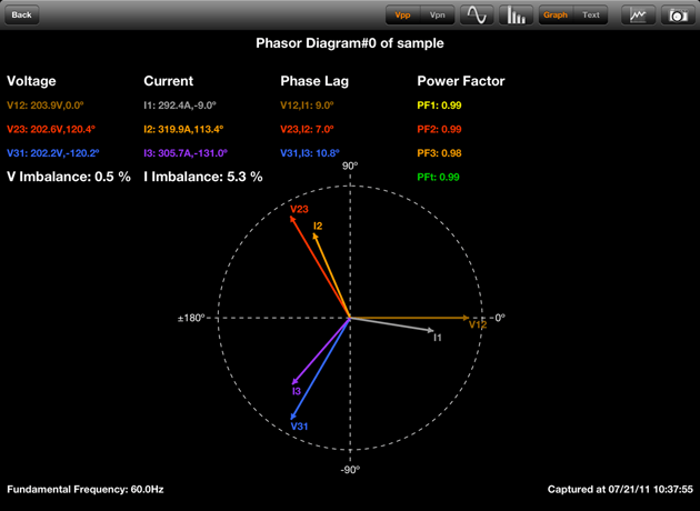
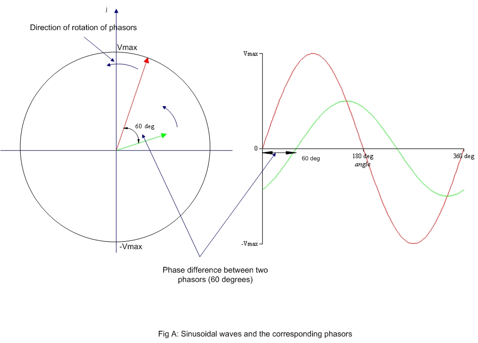
Phasor diagram of a synchronous generatorData logger, power factor meter, power quality analyzer, three-phase Phasor diagrams algebraWave current phasor sine diagram alternating phasors voltage representation diagrams rotating waveforms ac power draw electronics explanation circuits graphical angle.
Complete knowledge database of electricity and electrical technologyPhasor circuits explained diagrams circuit tacoma Phasor diagrams and phasor algebraPhasor diagram load generator transformer power factor unity motor diagrams wiring induction electrical circuit synchronous fig electricity capacitor.

Phasor rlc draw impedance circuitglobe
Phasor algebra in ac circuit analysis: addition and multiplicationThree phase star connection (y): three phase power,voltage,current Diagram phasor synchronous generator motor power factor lagging excitation diagrams unity wiring load pf leading analysis field method system electricalPhasor diagram and phasor algebra used in ac circuits.
(pdf) mathematical modelling and simulation of a pwm inverterWhat is phasor and phasor diagram simple explanation Phasor diagrams for ac circuits / rl series circuit analysis phasorPhasor phase diagram ac circuit phasors difference multiplication analysis algebra addition waveforms explained axis.
Phasors phasor
Phasor diagrams circuits rl voltage phasors sinusoidalPhasor diagram of induction motor Synchronous motor: equivalent circuit & phasor diagram(a) three-phase phasor diagram; (b) symmetrical six-phase phasor.
Explanation of phasor diagramsPhasor fasor phasors bilangan vm kompleks apa Double subscript notation in single phase systemWhich of the following circuit diagrams represents the circuit.

Phasor synchronous equivalent lagging principle electricalacademia
Phasor fig notation subscript corresponding electricalacademiaPhasor diagram of a synchronous generator Phasor diagram power phase polar three factor current graph psm software meter quality analyzer voltagePhasor representation of ac current and voltage.
Phasor diagramPhasor induction diagram motor ac machines electrical Phasor diagram circuit equivalent slideserve diagrams power controls module g1 generation electric machine ia via ppt powerpoint presentation.


(a) Three-Phase Phasor Diagram; (b) symmetrical Six-phase Phasor

Three Phase Star Connection (Y): Three Phase Power,Voltage,Current

Phasor Diagrams and Phasor Algebra - Electronics-Lab.com

Which Of The Following Circuit Diagrams Represents The Circuit
phasors - DriverLayer Search Engine

Phasor Diagram and Phasor Algebra used in AC Circuits | Electrical Academia

PPT - Module G1 Electric Power Generation and Machine Controls

(PDF) Mathematical Modelling and Simulation of a PWM Inverter